The Build
Welcome to the build , please ensure that you have your build pack , a pcb and a soldering iron and wire cutters.
Parts Check
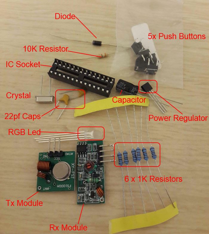
Ensure that your pack contains all the required parts.
1 x Diode
1 x 10K resistor
1 x 5V Power Regulator
1 x Smoothing Capacitor
1 x 16mhz crystal occilator
1 x IC Socket
1 x tx radio circuit
1 x rx radio circuit
1 x Atmega 328
1 x RGB LED
2 x 22pf capacitors
5 x Push buttons
6 x 1K resistors
Step 1
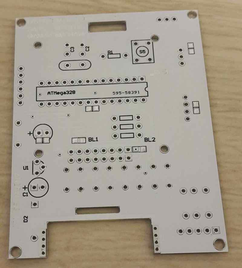
Flip the board so that is is aligned as in the picture below.
Step 2
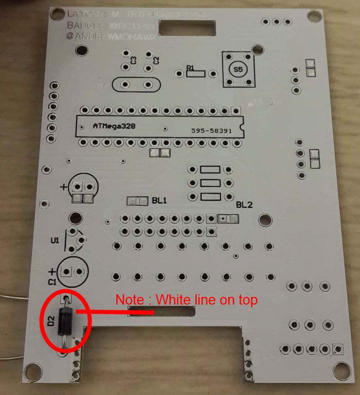
Next insert the diode into the first set of hole as seen below.
Once the diode is inserted flip the board around and bend the leads so that the diode does not fall out. Ensure that the white stripe on the diode is pointing to the top of the board as seen in the.
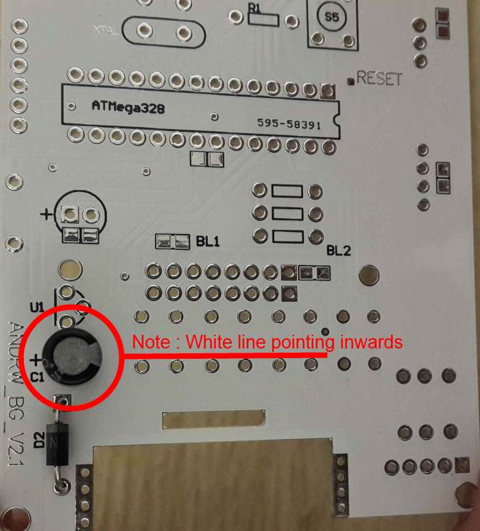
Step 3
Next insert the large black capacitor as seen below, it is the position just above the diode. Ensure that the white stripe on the capacitor is facing the inside of the pcb Once the capacitor is inserted flip the board and bend the leads so that the capacitor does not fall out.
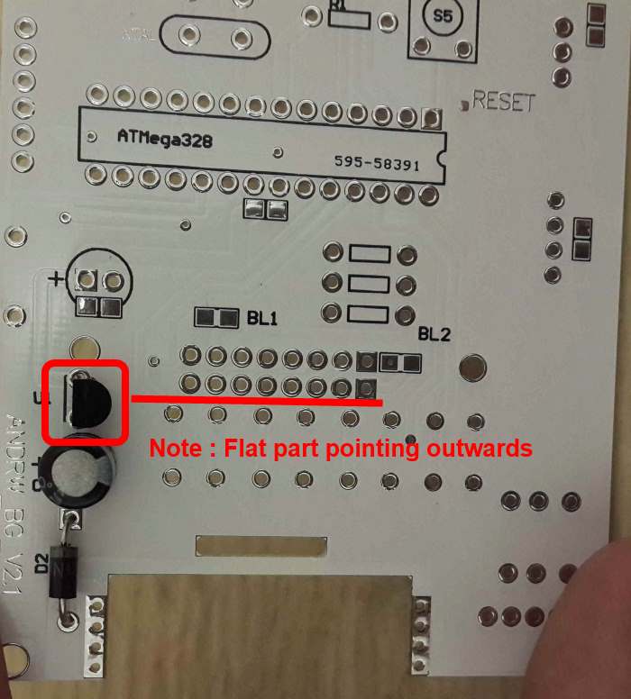
Step 4
Next insert the power regulator as seen below just above the capacitor. Ensure the flat side of the power regulator is facing the outside of the pcb , this can be confirmed by looking at the outline on the pcb. Once the power regulator is inserted flip the board and bend the leads so that the power regulator does not fall out.
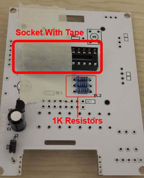
Step 5
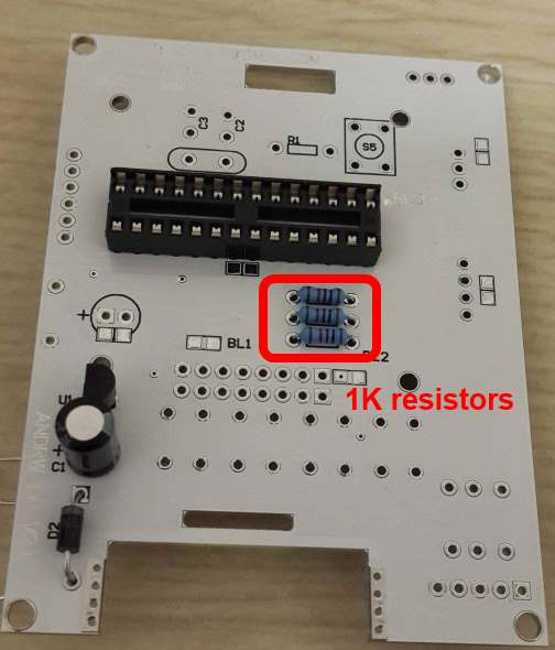
Next insert the IC socket into the area marked below. Once the socket is in place use a bit of masking tape to hold it down.
Next Insert 3 1K resistors into the area just below the IC socket. Once they are in place , bend their leads to ensure they are held in place.
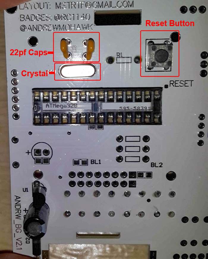
Step 6
For the following step please use the image below as a referene.
Insert 1 button into the area labeled S5 to the right of the 10K resistor
Next insert the crystal into the area just above the IC socket to the left of the R1 resistor. Once the crystal is inserted , bend its leads slightly to ensure that it does not fall out when the board is turned around.
Next insert the 2 22pf caps as seen in the pic below. Ensure that the capacitors are not paralel to the crystal.
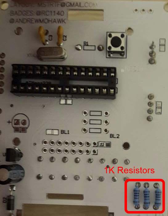
Step 7
Next Insert 3 1K resistors into the bottom right corner as seen in the pic below. Once they are in place , bend their leads to ensure they are held in place.
Step 8
Note : Before starting with the soldering , get one of the assitants to check that all your parts are in the correct location and in the correct orientation.
Now flip the board over and solder the parts that have been inserted.
Next clip of any extra wire above the solder joints as seen in the pic below.
Once that is done flip the board over remove the masking tape from the socket holder.
Step 9
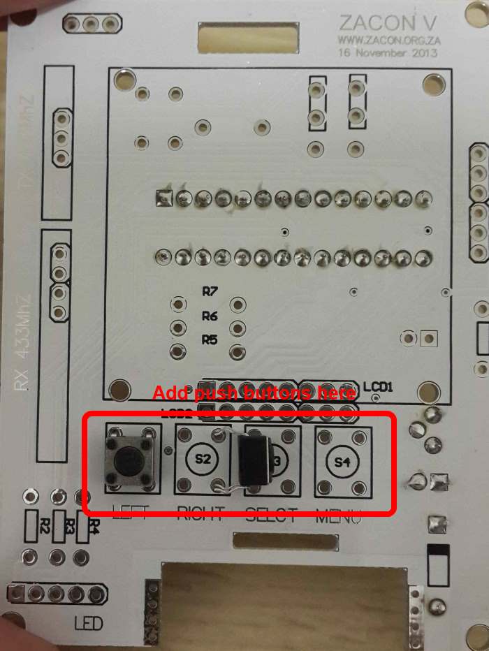
Next flip the board over again and Insert 4 buttons into the sections labeled S1 - S4. Note the board orientation (The chip holder should be on the back of the board).
Step 10
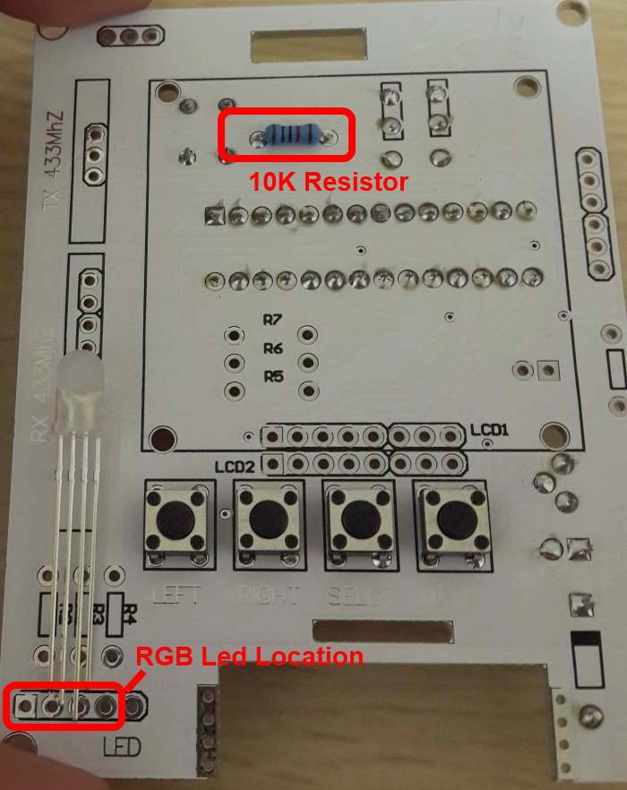
Next Insert 3 1K resistors into the bottom right corner as seen in the pic below. Once they are in place , bend their leads to ensure they are held in place.
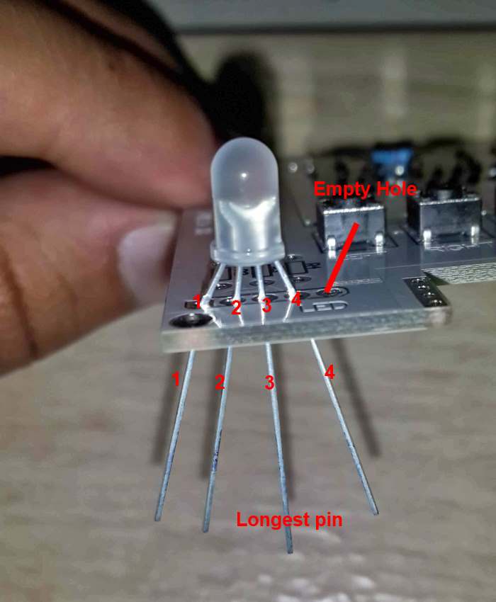
Insert the RGB led as seen in the pic below, when counting from the left the ground pin should be inserted into pin 3 and pin 5 should be empty.
Pin out for RGB Led :
Step 11
Next Insert the 1 10K resistors into the area just above the IC socket , to the right of the reset button. Note : While the 10K resistor is labeled , its label is on the reverse side of the board. Once it is in place , bend its leads leads to ensure it is in place.
Step 12
Flip the board over and solder the connections for the parts that were just added.
Step 13
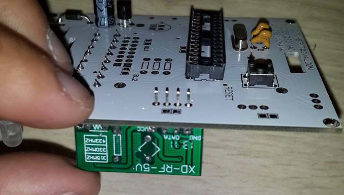
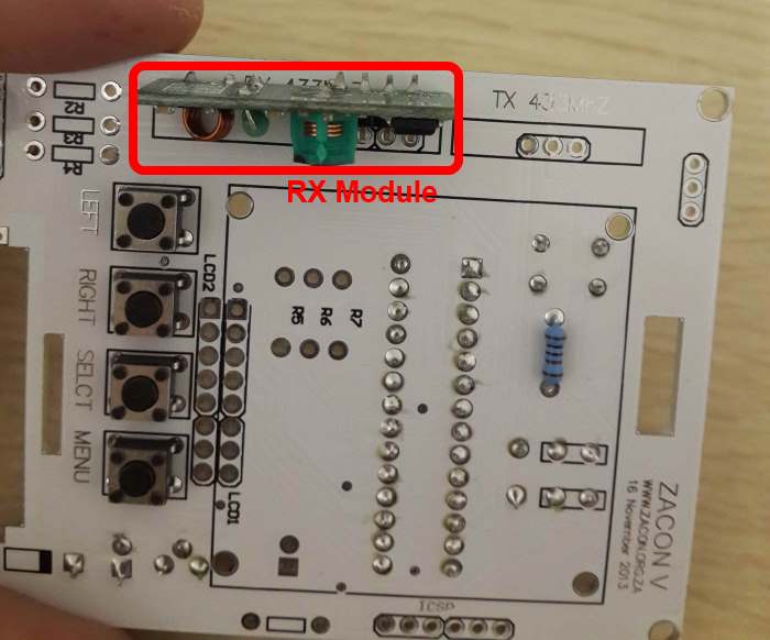
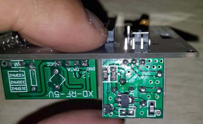
Next insert the rx module into the area labeled rx as seen in the pic below.
Now while holding the rx module in place flip the board as shown below and solder the connections for the rx module.
Step 14
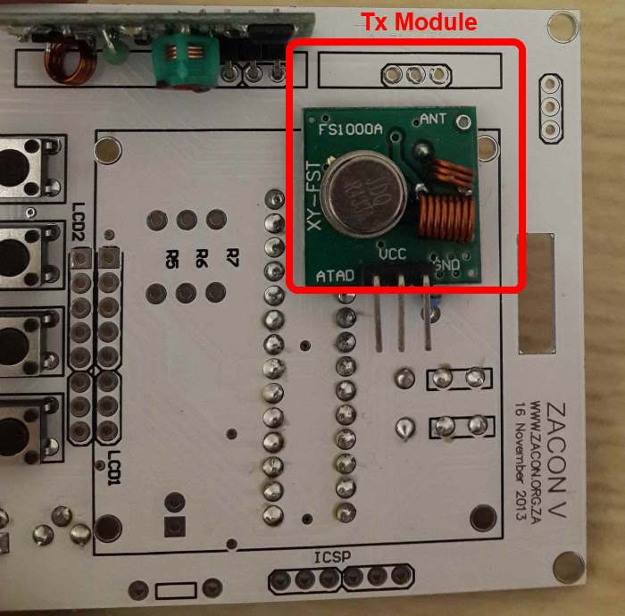
Next insert the tx module into the area labeled rx as seen in the pic below.
Now while holding the tx module in place flip the board as shown below and solder the connections for the tx module.
Step 15
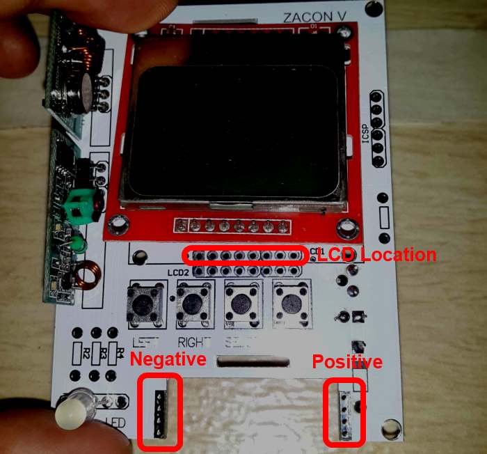
Finally insert the power connectors into the battery area and solder them in place, The spring should be used for the negative terminal while the flat connection is used for the positive terminal.
Finally insert a chip and get the board tested , if the board passes all its tests solder the lcd into the location labeled LCD1.